Using Simulation Template
Since often times you would need to work on an existing simulation (“simulation” refers to the files including the model), change it a little bit, apply them to a specific model and export it again for another run, we focus on this process in this section.
Loading a Simulation File
Once a model has been loaded into ModelBuilder, the simulation file can be added.
Click File-Open, Load Simulation Template or Load Simulation to load a
simulation file. The “Open”  button on the File IO tool bar can be used
as well.
button on the File IO tool bar can be used
as well.
Editing a Simulation File
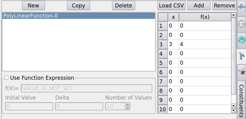
Let’s use test2D.cmb used in the last section and AdHSurfaceWater.crf as an example. Suppose we want to edit the “function” tab. Click on the “function” tab on the right-hand side of the “Attribute” tab, you will see a tabular of a poly-linear function f(x) by default. Enter (3, 4) in the third row.
Next we define a material. Clicking on the “material” tab brings up a window as the figure below:
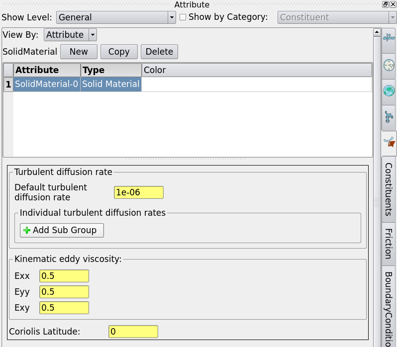
Clicking on “New” to create a new material, physical parameters can be further specified, we use the default values here.
Associating with Model
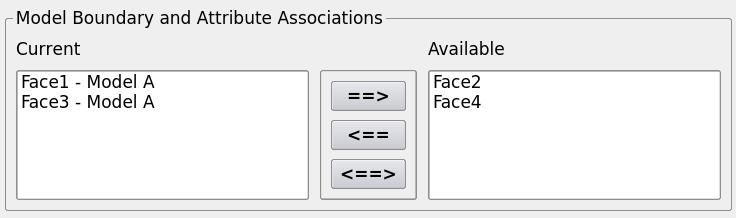
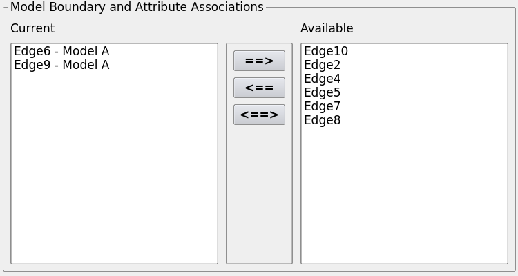
After creating the material, we want to associate geometry to it. There is a “Model Boundary and Attribute Associations” tab in the material tab. The faces are categorized into “Current” and “Available” groups where the former means the ones associated with the current material, and the latter indicates that they are not associated to any material. The buttons in the middle moves the entities left and right.
We can also assign boundary conditions to the model. Click on the “BoundaryConditions” tab, a variety of boundary conditions can be specified in the dropdown menu such as velocity, lid elevation, water depth lid and so on. In this case we create a “Total Discharge Boundary Condition” and a “Unit Flow Boundary Condition” individually.
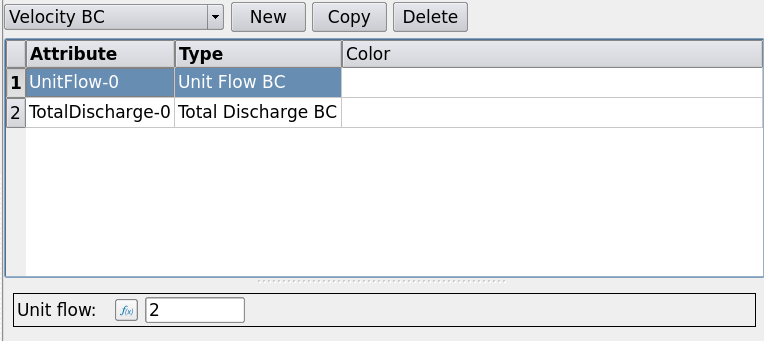
Each boundary condition requires a numeric value to be specified. Similar to the material, edges can be associated to those boundary conditions we just created.
Saving a Simulation File
To save a simulation file to load in the future, go to the File menu and select “Save Simulation”. Now you are safe to exit ModelBuilder. Next time the model and simulation are opened, everything we modified will be loaded.
Note
The save process will save both the template and the values into one file. If you are expecting to configure multiple simulations from the same template, do not overwrite the original template file.
Exporting a Simulation File
Once a simulation and its attributes have been finalized, you can export by going to the File menu and selecting “Export a Simulation File”.
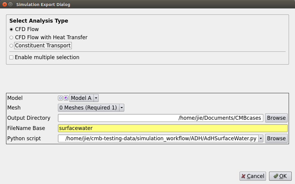
Multiple analysis can be selected for exporting. In this example we did not mesh the model so ModelBuilder will use the underlying vtk mesh as the mesh. Output directory, filename and Python exporter should be specified.
Click “OK”, you can see “surfacewater.2dm” and “surfacewater.bc” are generated in the output directory. The first file contains the geometry information of the model and the second one contains the boundary conditions. They are ready to be used in ADH solver.